


4(5) 2008
 |
|
 |
ARCHITECTURE AND MODERN INFORMATION TECHNOLOGIES
МЕЖДУНАРОДНЫЙ ЭЛЕКТРОННЫЙ НАУЧНО-ОБРАЗОВАТЕЛЬНЫЙ ЖУРНАЛ ПО НАУЧНО-ТЕХНИЧЕСКИМ И УЧЕБНО-МЕТОДИЧЕСКИМ АСПЕКТАМ СОВРЕМЕННОГО АРХИТЕКТУРНОГО ОБРАЗОВАНИЯ И ПРОЕКТИРОВАНИЯ С ИСПОЛЬЗОВАНИЕМ ВИДЕО И КОМПЬЮТЕРНЫХ ТЕХНОЛОГИЙ
TYPING THE SHAPE OF A BUILDING: ZONING PLANNING SUPPORT TOOL FOR INDIVIDUAL PLOTS IN ARCHITECTURAL DESIGN
D. Donath, D. Lobos, (Д. Донат, Д. Лобос)
Bauhaus-University Weimar, Germany
http://infar.architektur.uni-weimar.de
1. Introduction
Since Hugh Ferris in 1922 started with a series of massing studies the visualization of zoning planning began to be a topic for architects. Setbacks, plot area ratio, maximum building height, and other important attributes must be handled by the architect to fulfill the law, the needs of the clients and his own inspiration. This paper presents the problem of envelop design for high-rise isolated housing buildings, as well as a new Decision Support Systems tool based on the platform of a BIM software, that allows to simulate several options for building envelope according to the parameters required by the city Zoning Planning. These options deliver reliable data and geometry, to be analyzed in real time for the architects, engineers, builders, government and the client in the early stages of the building's design.
The current research contributes with a new approach because it analyzes the building from a normative point of view (Lobos, 2006), but also including the variables of the client and the architect. Whose have an influence on the final shape and size of the building envelop. In this paper we present a solution for Space Program and Urban Codes.
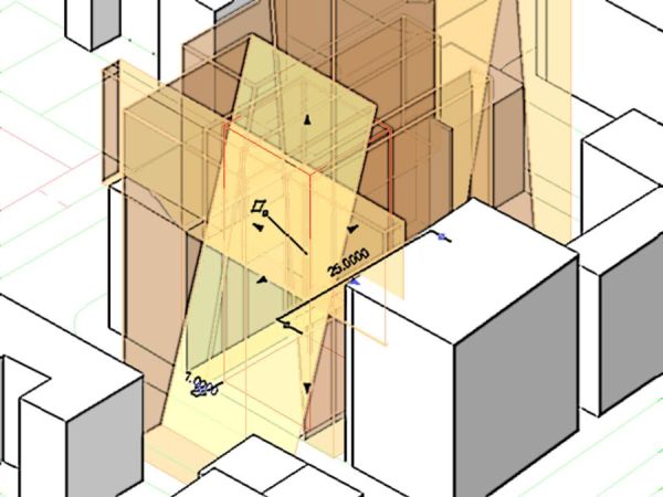
This process of the early and schematic definition of the shape and size of the building is included in the Urban Regulations different of countries and it is well-known as “massing study”, “maximum building bulk” or “theoretical volume” that is a tridimensional volume, similar to a paralepipedo (polyhedron of six faces) with additions or subtractions according to the application of different urban codes (Fig.1). This operation has to be done as a part of the folder for the Government Building Permission.
 |
|
Fig. 1.The Zoning Planning applied to a plot in the city. Self Elaboration 2007 © Lobos |
2. The Early Stages of Architectural Design Process
The research is focused on the early stages of architectural design process. In this stage take place the creation and analysis of the Theoretical Volume and the final building envelop. The decisions made in this stage are irreversible, so, the most important. Some approaches to the definitions and tasks of these “early stages” are discussed widely by Lewis (1998), Lyon (2002), we considerate the IBC (International Building Code), on which Patten (2003) highlights that all of the services provided by an Architecture office can be divided in 5 steps, the first is called Schematic design phase (15 % of the total services) and considerate: Programming, Space Diagrams, Site Development Planning, Site Utilization Studies, Utility Studies, Environmental Studies, Zoning.
3. Variables
3.1. Variable1: The Space Program
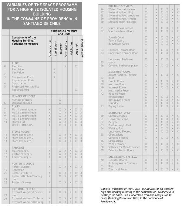
The Space Program is a transcription, or a translation, of the needs of the client into an architectural programmatic language, this means, words and numbers able to be interpreted by the architect into rooms, sizes and relationships. Here the spaces and their sizes must be scheduled (names and areas) named, listed, grouped by zones. We propose the use of a Digital Database represented by Dynamic Shared Table (a Microsoft Excel spreadsheet table) to store, edit and exchange, quickly the required data from the building. In our case (apartments) data will be: Number of users, number of Flats, sleeping rooms per Flat, store rooms, parking, Porter’s Lodge, Building Services, multiuse rooms, green surfaces, circulations, engineering systems, etc, as shown in Table1.
|
Table 1. Variables of the SPACE PROGRAMM for an isolated high-rise housing building in the commune of Providencia in Santiago de Chile. |
 |
3.2. Variable2: the Urban Code
The origin of the use of theoretical volumes is completely linked to the existence of the Urban Planning, particularly to Urban Regulations, since the (Athens Charter, 1933), and the Seagram Building (Ludwig Mies van der Rohe and Philip Johnson, 1958).
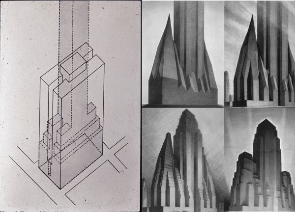
The New York City 1916 Zoning Resolution was a measure adopted primarily to stop massive buildings such as the Equitable Building in Manhattan (Fig. 1) from preventing light and air from reaching the streets below. It established limits in building massing at certain heights, usually interpreted as a series of setbacks and, while not imposing height limits, restricted towers to a percentage of the lot size. The 1961 Zoning Resolution coordinated use and bulk regulations. Architectural delineator Hugh Ferriss popularized these new regulations in 1922 through a series of massing studies (Fig. 2), with a series of “zoning envelope” studies; these illustrated how the maximum building volumes permitted by New York's setback zoning laws of 1916 could be incrementally refined into finished building designs.
 |
|
Fig. 2. Equitable Building NY and Hugh Ferriss works ( www.enigma_foundry.com: may 2008) |
There are more than 10 rules to apply at the same time, only in the early stages of the architectural design of a high-rise building. These rules come from three main resources: the Building Code (each country), the Local Ordinance (each commune or district), and the Site Information Report (each plot). By using these rules it is possible to design many different shapes, starting from the “maximum theoretical volume”.
Our implementation will considerate the following Zoning Planning regulations: site size, Buildable coefficient (Plot/Area Ratio), Site coverage coefficient (Coverage Area), Setback requirements, Sky exposure plane, Maximum Building height, Story height, Underground levels (height and total depth).
1. Buildable coefficient (built area or Plot Area Ratio-PAR): is a non-negative real value that multiplied by the total area of the plot, determines the maximum gross floor area (square meters) of the complete building (value 1-10, increasing in ten decimal range: 1.1 – 1.2 - etc), regardless of its shape.
2. Site coverage coefficient: is a non-negative real value that multiplied by the total site area, determines the maximum ground floor area of the Ground Level of the building. The value ranges in tens, from 0 to 1 (0.1 – 0.5 – 0.6 - etc) or percentage in tens (10% - 50% - 60% - etc).
3. Setback requirements: determines the minimum horizontal distance allowed between each lot line of the plot and the nearest point of the building. Different codes for this requirement depends on the country, it varies as high as the building is. It applies in different parts of the height of the building.
4. Sky exposure plane: imaginary plane that cuts the theoretical volume, it starts from each lot-line following a defined angle upwards and inside the site (60°, 70°, 80° are possible values).
5. Building height: determines the maximum vertical distance allowed between the natural ground level and the highest point of the building.
6. Story height: determines the minimum allowable vertical distance between the finished floor and the ceiling of an inhabitable room (e.g Chile = 2.35 m).
7. Parking: every building must be designed with a minimum quantity of parking, determined by the Local Ordinance. As general practice 1 parking per flat and the 10% is in the surface of the plot and the rest is in the Undergrounds.
8. Shadows: Shadows over the neighborhood must be quantified. This variable will be included in the next version of the prototype.
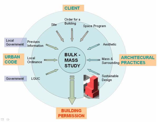
As a summary these variables are related to three main areas: the Space Program, the Urban Codes and the Architectural Practices. These, according to our approach, determine the shape and size of the final envelop of a high-rise housing building in the early stages of design (Fig. 3).
 |
|
Fig. 3. Diagram for the paperwork after the full Government Building Permission. |
4. CAAD Prototypes
4.1. Cadastre for existing Commercial Software
It will be taken into consideration the results from Lobos (2007), and his cadastre for the existing commercial tools for Architecture. The analyzed tools were grouped in three areas: 1. Design Software for Architecs: Autocad 2d/3d, Maya, FormZ, Sketchup, Maxxon Form, Rhinoceros, Paracloud, Ecotect, Generative Components, and Affinity. 2. BIM/AEC Software: Revit building, Archicad, MicroStation, Architectural Desktop, Allplan, Catia / Designer, Vectorworks. 3. 3d Model& Animation Software: 3dsmax, Cinema 4d, Quest 3d, Autodesk VIZ, Softimage.
There was concluded that actually there is no commercial application that resolves the complete problem. In the most of them it is possible, and necessary, to develop new solutions for these new tasks by creating new ones in a programming language (Plug-in or Add-ons)
4.2. Cadastre for existing Prototype Software
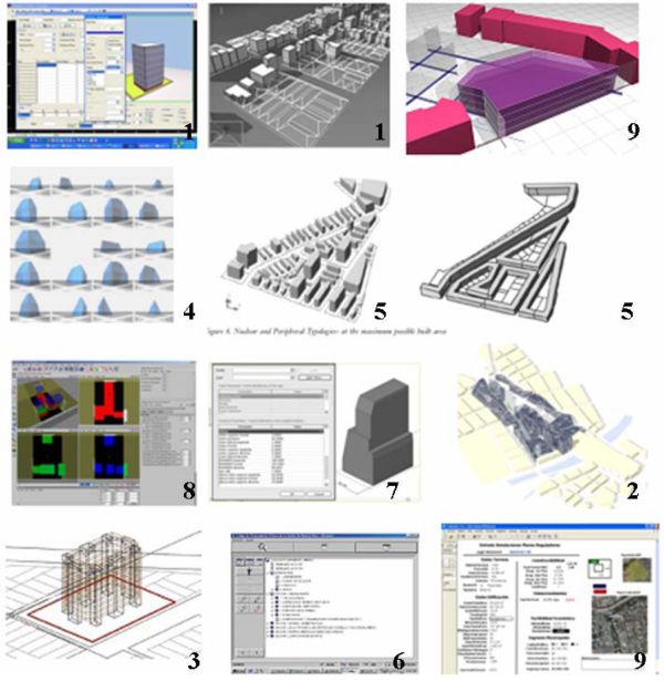
Next we present the current state-of-the-art in prototype tools for the urban code tasks. We will divide the works in two categories: those that work over several plots (Urban Planning in blocks) and those that work in one plot (Architectural Design in one plot). In both cases we have find useful but partial solutions. Recent researches tend to support, but partially, this process by creating some new ICT Tools (Fig. 4).
 |
|
Fig. 4. Cadastre for existing Prototype Software |
4.2.1. For several Plots
1. Cityzoom (Grazziotin et all, 2004). A Decision Support System for urban planning, with a specific built-in city model, where data is represented in an object-oriented model representing the urban structure, to simulate the impact of alternative urban regulations for large number of plots. Results can be displayed as tables, graphs, and in a 3D preview.
2. Neuplanung Umfeld Hauptbahnhof Zürich (Kaisersrot und KCAP, 2007). Use of the visualization of Zoning Planning regulations to support the design ideas.
3. C-Code 1.0 (Labarca and Culawgosky, 2006) Programming on AutoCAD the automatic generation of guided-style theoretical volumes and finished building envelopes for several blocks.
4. Normativa 3d (Wurman, 2006). To evaluate the Zoning Planning Tools through their tri-dimensional modeling, representing in graphic and visible way the target-image or the urban shape for the city.
5. A City Simulator Raposo et all (2001). To simulate and analyze cities where tall buildings are emerging on pre-existing urban schemes with irregular shapes.
4.2.2. For one Plot
6. Building Code from GIS linked to Internet: several researches (Erba and Uribe, 2005; Marambio and Garcia, 2005); Frassia (1999).
7. Parametric Envelope (Melantoni, 2006) creation of prototypes in REVIT, the Urban Code is turned to a computable data (input) and the tool shows an automatic theoretical volume (output) in real time.
8. BDS: Building Bulk Design Support Tool (Gonzalez, 2005) and Donath and Gonzalez (2006) a constraint-based design strategy to support participatory housing planning processes. Explains the implementation criteria of a constraint satisfaction approach to solving the building bulk design problem.
9. Spaceplan (Tonn, 2002) Bauhaus-Uni Weimar. A tool for planning and optimization of basic building regulations in urban plots. Input: plot size, setbacks, Plot Area Ratio, Maximum Occupation. Output: 3d volume optimized by Total Area or Total Stories.
10. Simulador PRU_Datos: a tool developed by (SOLNET S.A., 2005). For Economic Simulation and Profitability of the plots in a district or commune.
The most of these authors have created very useful tools to support larger Urban Design/Planning decisions or working on a specific plot. But none of them considerate the total number of codes of our case.
4.3. Parametric Model in REVIT
We introduce a new tool, called “Prototype for Urban Code constraints”, and developed by Danny Lobos. Taking into consideration the required variables for the design of a theoretical volume of a building it was chosen the BIM software Autodesk Revit Building ® because of the simple and powerful 3d modeling visualization and the possibility to add the parametric constraints to the classical 3d Boolean Operations, through the use of Parametric Families function, as described by Melantoni (2006). Implementation: Windows XP, CPU Intel Core Duo 1.66 GHz, and memory 1 GB.
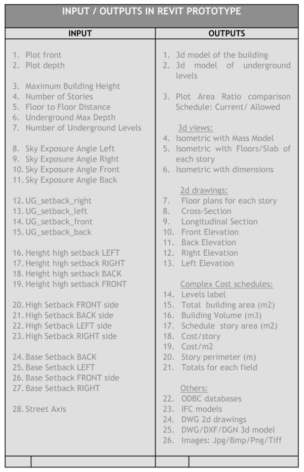
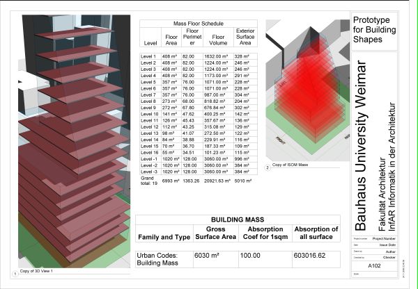
Once we calculate the total area (min-max) for the building in the Space Program Database (developed in Microsoft Excel), we are ready to model several scenarios in a plot. Starting from a generic box volume, constraints are added and they act as Boolean operators, mainly subtracting mass to the original volume, as described in (Gonzalez, 2005). The values of the codes (plot sides, setbacks, sky exposure angle, maximum building height, undergrounds depth, etc) (Table 2) can be added by the architect as a text format in a user friendly interface and see the changes of the shape and size of volume in real time (Fig. 5), then he can get automatically several reports on each scenario:
3d views/floor/section/elevations plans, total area of the building (m2), volume of the building (m3) and area per story (m2), perimeters (m), costs, ODBC databases, IFC models.
|
Table 2. Input/outputs in Revit prototype |
 |
 |
|
Fig. 5. Screenshot of “Prototype for Urban Code constraints”, developed by Lobos (2007) |
It must be considerate, for the future, the integration of the API features to work with the other detected variables. The Autodesk Revit API (Advanced Programming Interface) can be accessed fully by any language compatible with the Microsoft .NET Framework 2.0 (Visual Basic .NET or Visual C#). Due to the reviewed literature and the current available software knowledge, it must be considerate also the capabilities of other languages for these complex tasks: Programming with AutoLISP (for AutoCAD/ADT), Programming in JAVA, Iconic Programming (Quest3d/Cinema4d), and Script for (3dsMax / Rhino / Generative Components).
Conclusions
We have revealed the phenomenon of the envelope design for high-rise apartment building. We have found and described its variables and then we have created a tool that generate new optimized building envelops for a plot. The results of this proposal show that the use of specific ICT Tools in the early stages of a building design helps to reduce the working time, increases the confidence on the generated solution and it also contributes to the exploration of several alternatives in a short time. The next step will be to distribute the space program into the boundaries of each floor.
We have provided the basis for the creation of a new concept: Plausible Optimal Envelop, which defines the optimal relationship between different variables in this stage of the planning process (client - urban codes – architect). This process and methods could be extended to other type of buildings: health, education, commerce, etc. The possibility of using IFC codes in each stage must be mentioned, it helps to exchange information among all software platforms and applications used in each stage and all of the involved players of the building process. The constructors, engineers and others players could have information about the building in early stages of the design to work on their fields.
References
Donath, D. and Gonzalez, L.F.: 2006, A constraint based Building Bulk Design Support, Sigradi X, Santiago de Chile, pp 278-282.
Frassia, M.:1999, Código Digital de la ciudad de Buenos Aires. Sigradi III Montevideo, pp. 209-212
Grazziotin, P.C.; Benamy; T.; Sclovsky, L.; Freitas, Carla M. D. S. : 2004, Cityzoom - A tool for the visualization of the impact of urban regulations, SIGraDi [Proceedings of the 8th Iberoamerican Congress of Digital Graphics] Porte Alegre – Brasil, pp 216-220.
Lewis, R. K.: 1998, Architect: a candid guide to the profession, Cambridge - Mass, MIT Press.
Lobos, D.A.: 2006, Diseño Plausible de Plantas de Piso. Una metodología asistida por IT Tools, Proceedings of the 10th Iberoamerican Congress of Digital Graphics (SIGRADI), Santiago de Chile, pp. 293-298.
Lobos, D.: 2007, Plausibility in Early Stages of Architectural Design: the case of Theoretical Volume in Santiago de Chile, Technical Report for Research Theme – 2007, INFAR - Bauhaus-Uni Weimar.
Lyon, E.: 2002, Strategies for IT Adoption in the Building Industry, Graduate Research Seminar, Georgia Institute of Technology, pp. 9-11.
Mellantoni, G.: 2006, Sólido Capaz: Modelamiento Parametrico de Distanciamientos. Revit Workshop, SIGraDi X, Santiago de Chile.
Patten G., J.: 2003, The Architect’s Portable Handbook. First-step rules of thumb for Building Design. Third Edition, 0-07-142889-5, McGraw-Hill,
Raposo, M.; Sampio, M.; Raposo, P.; Camara, A.; Batista, A.; Andrade, F.: 2001, A City Simulator. ACADIA, ISBN 1-880250-10-1, New York. pp 52-61.
Wurman, D.: 2006, Normativa 3D. La modelación tridimensional como método de evaluación y herramienta de generación de la normativa. Tesis Magister en Arquitectura, Universidad Catolica de Chile.
